Product Details
- Brand: Curt
- Model: 13215 56270 57187 58303-CH3388
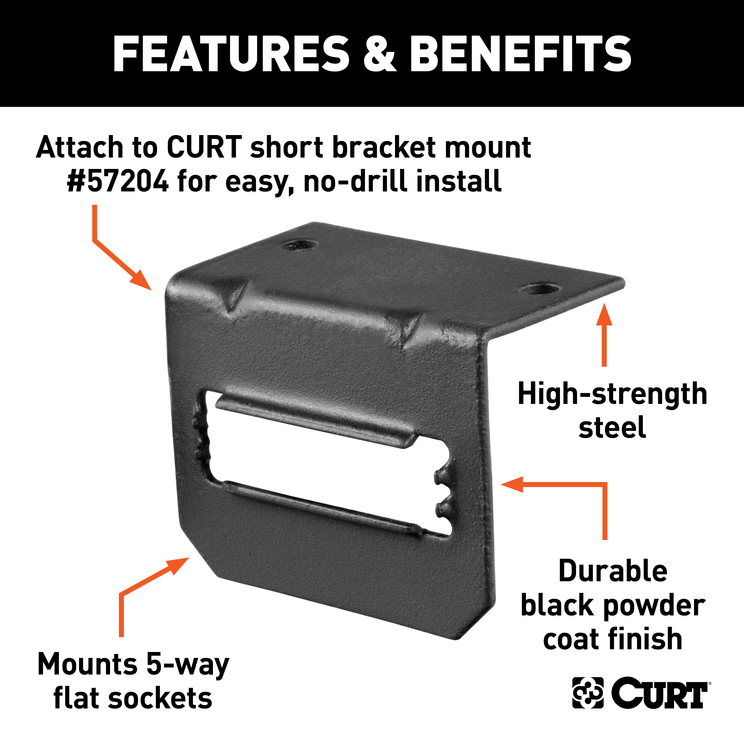
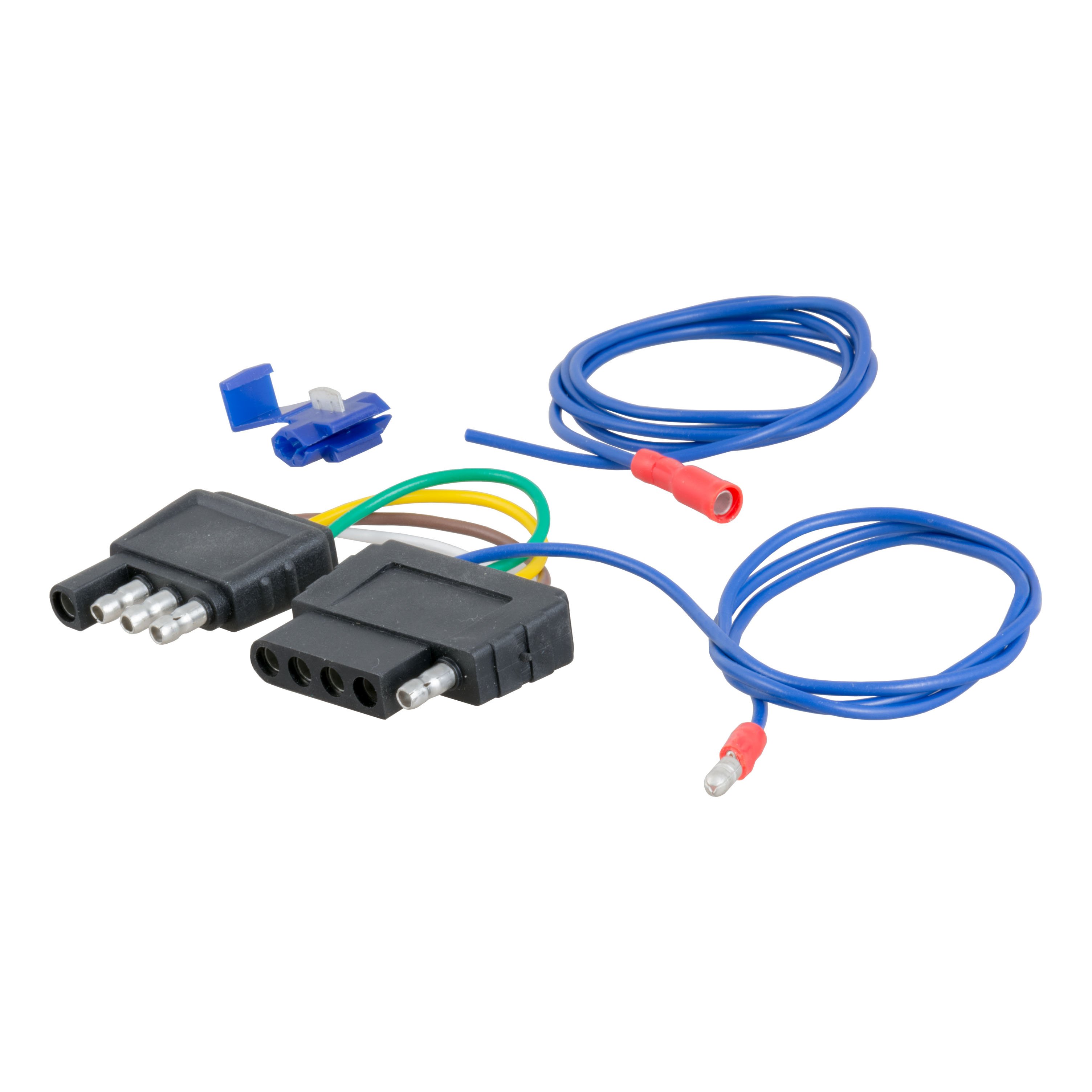
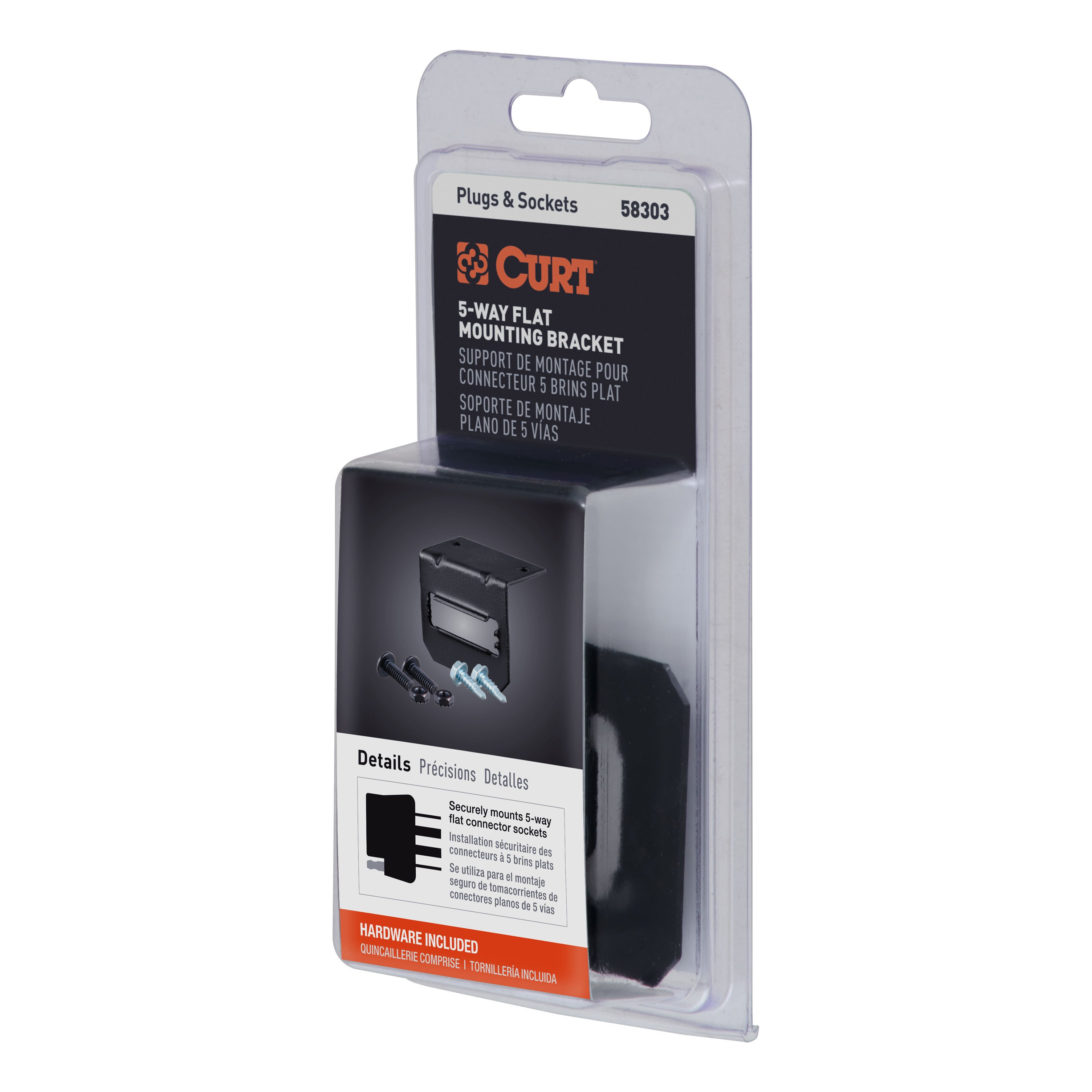
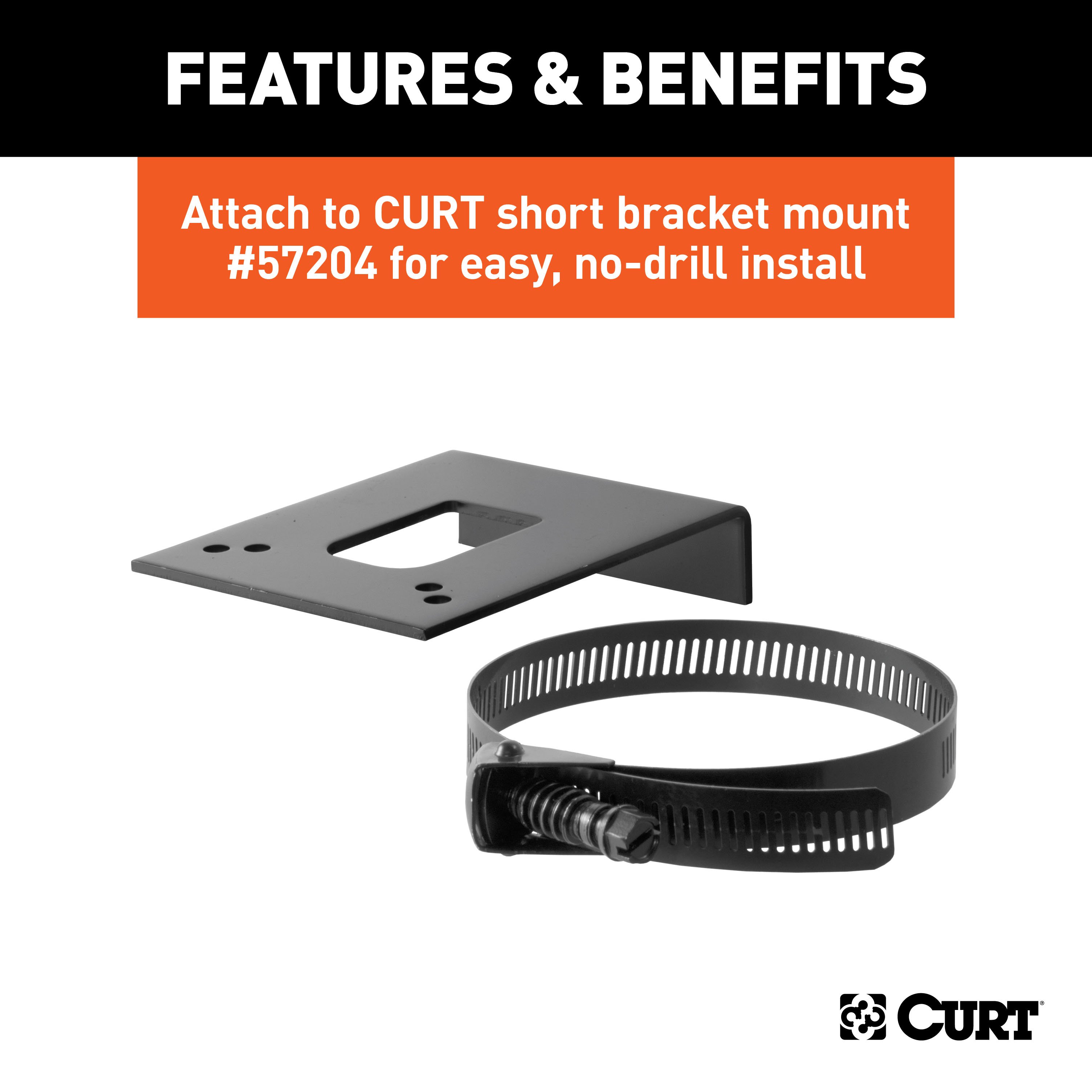
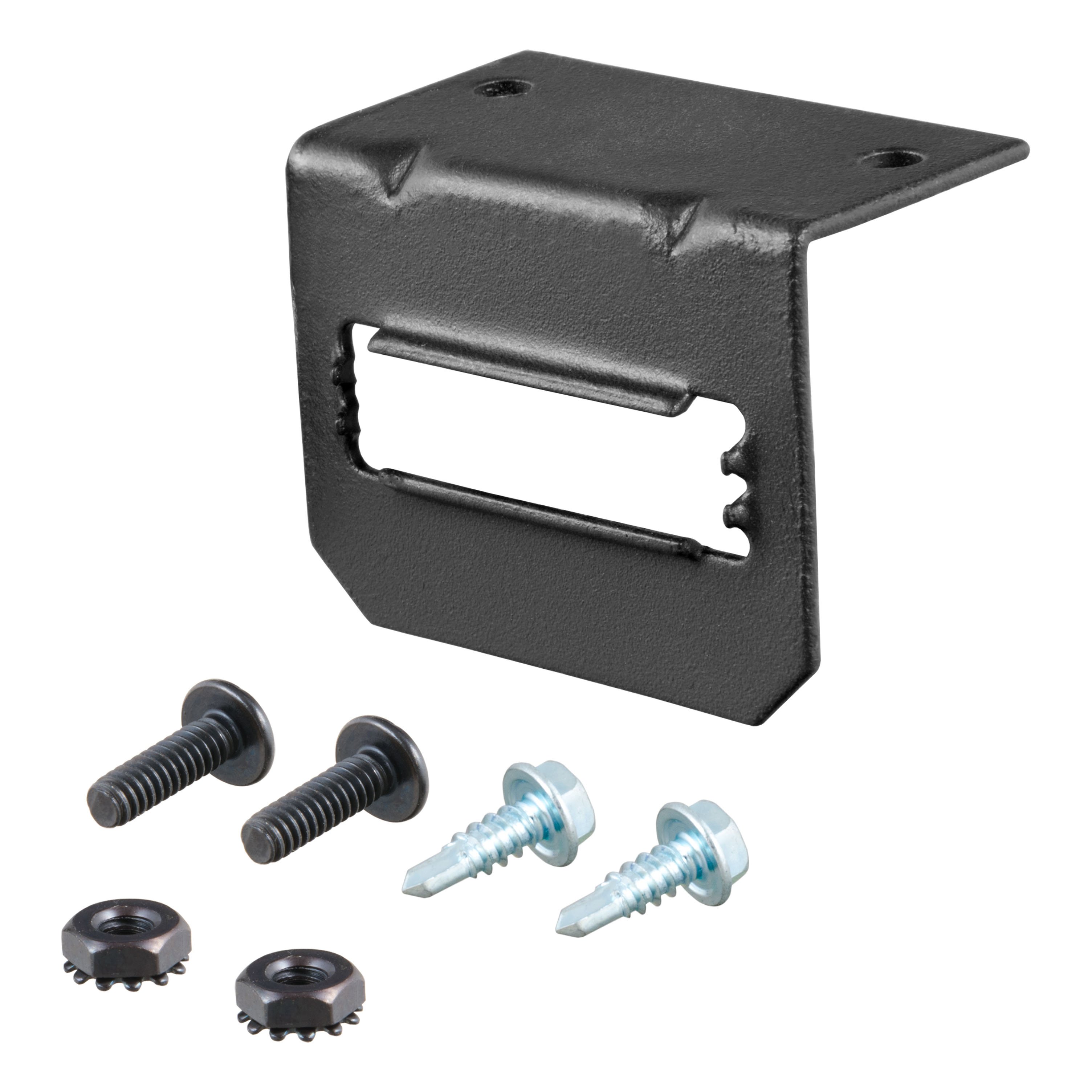
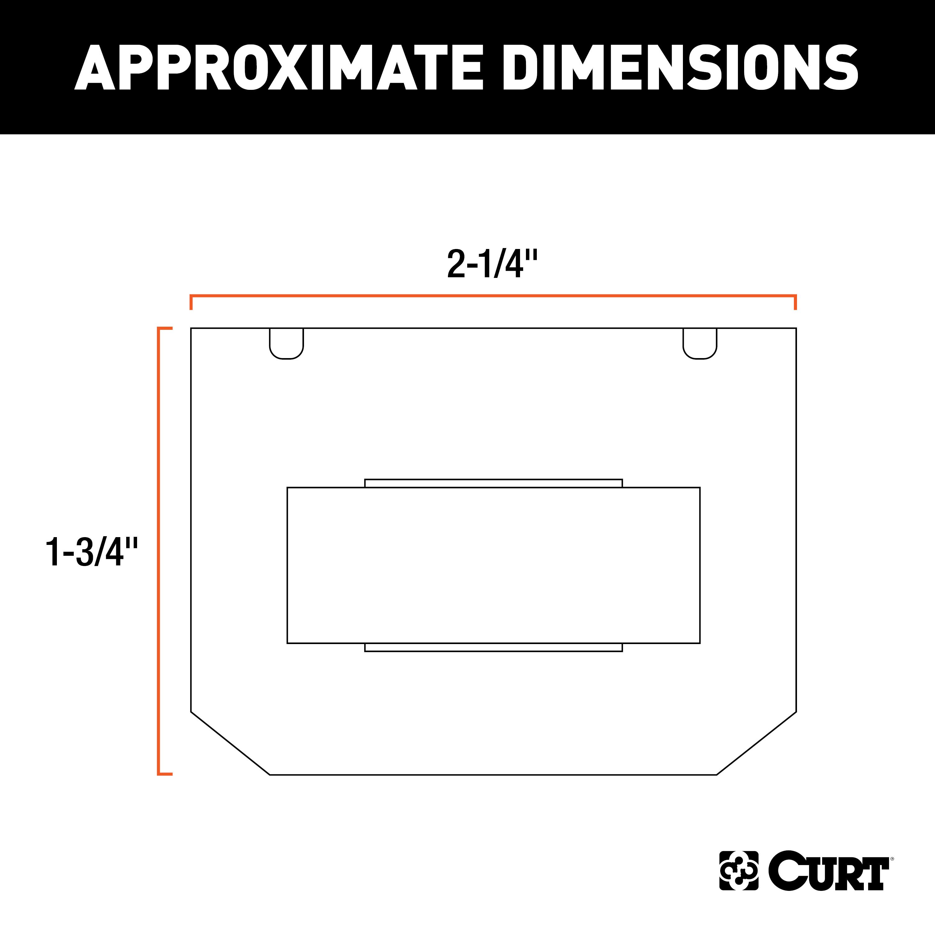
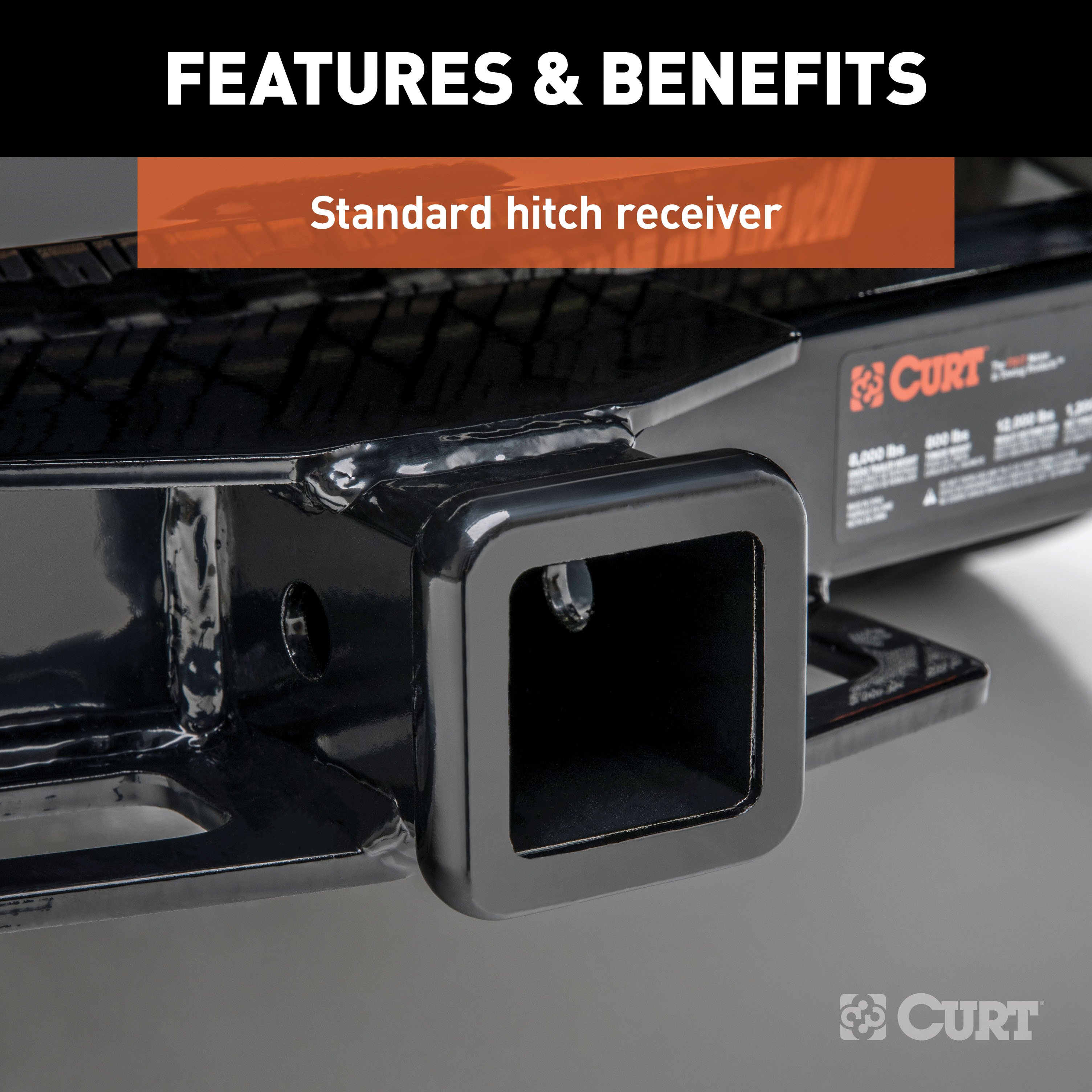
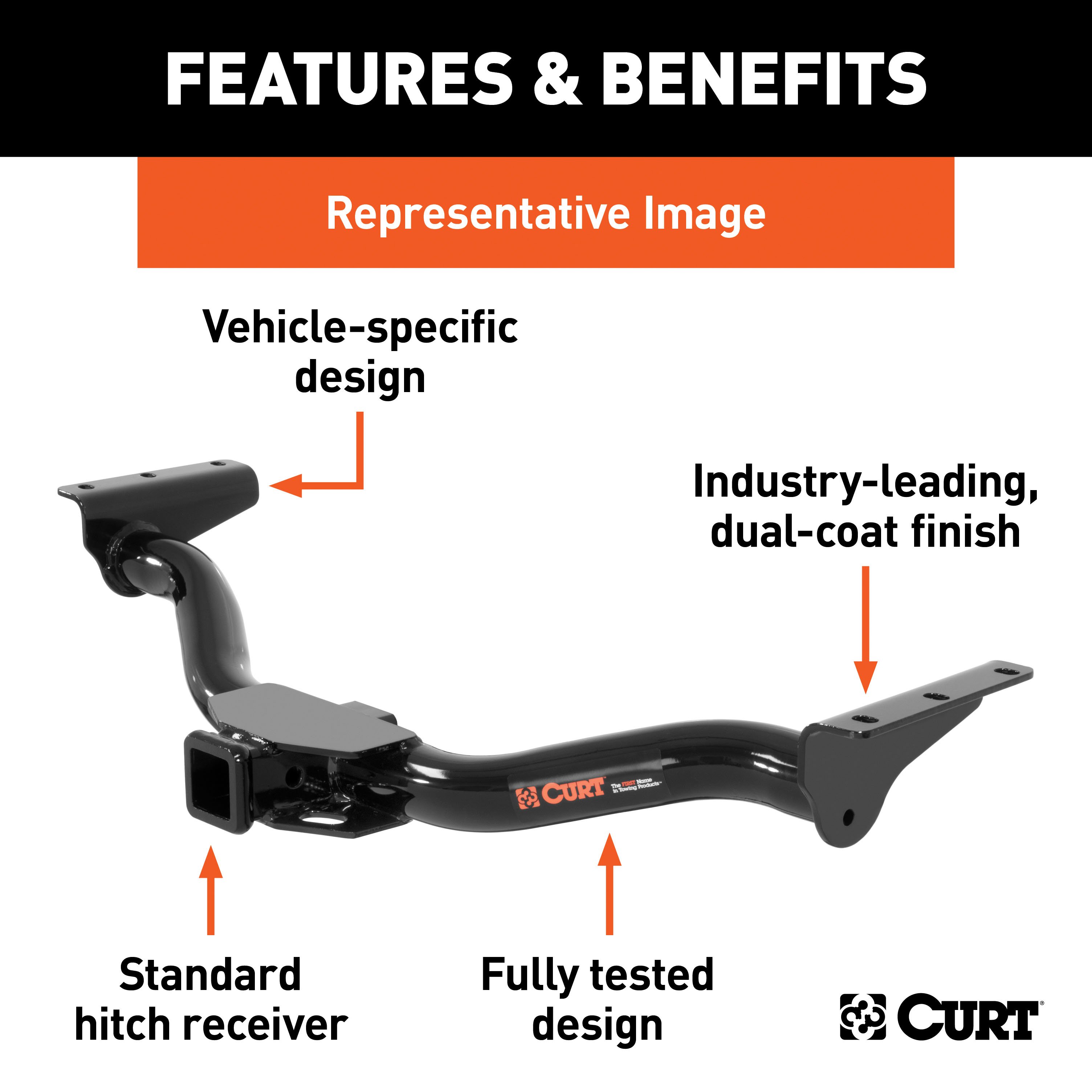
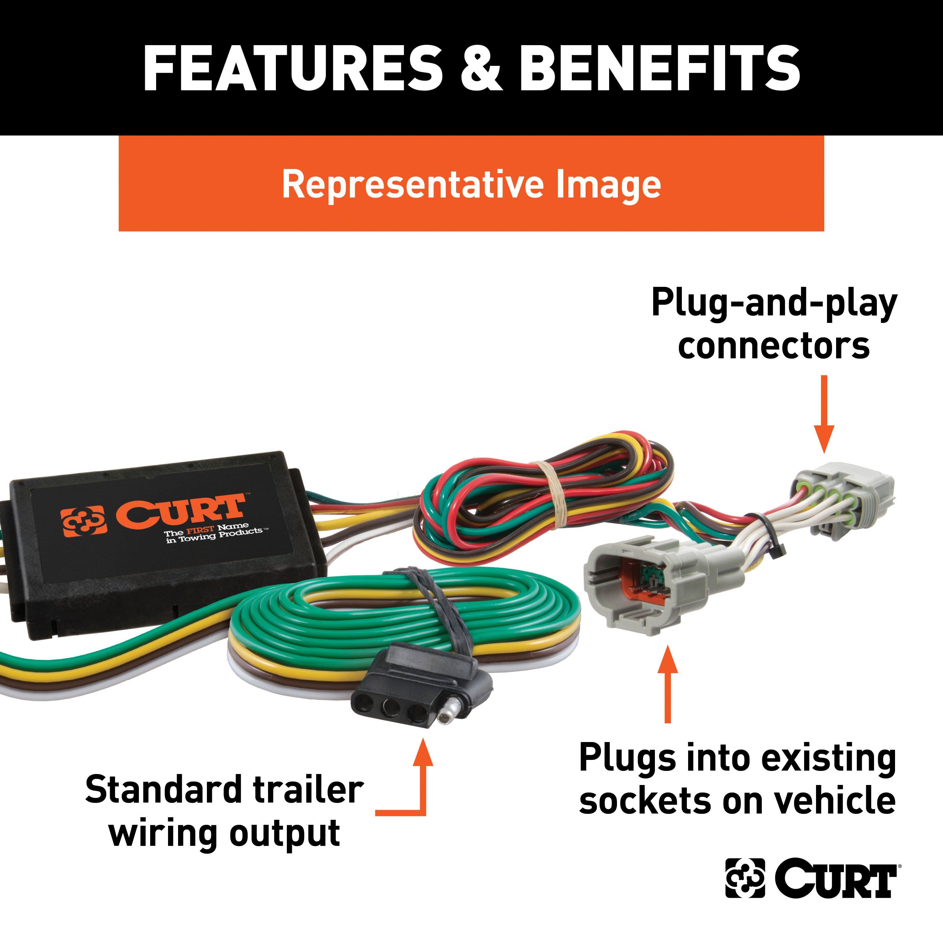
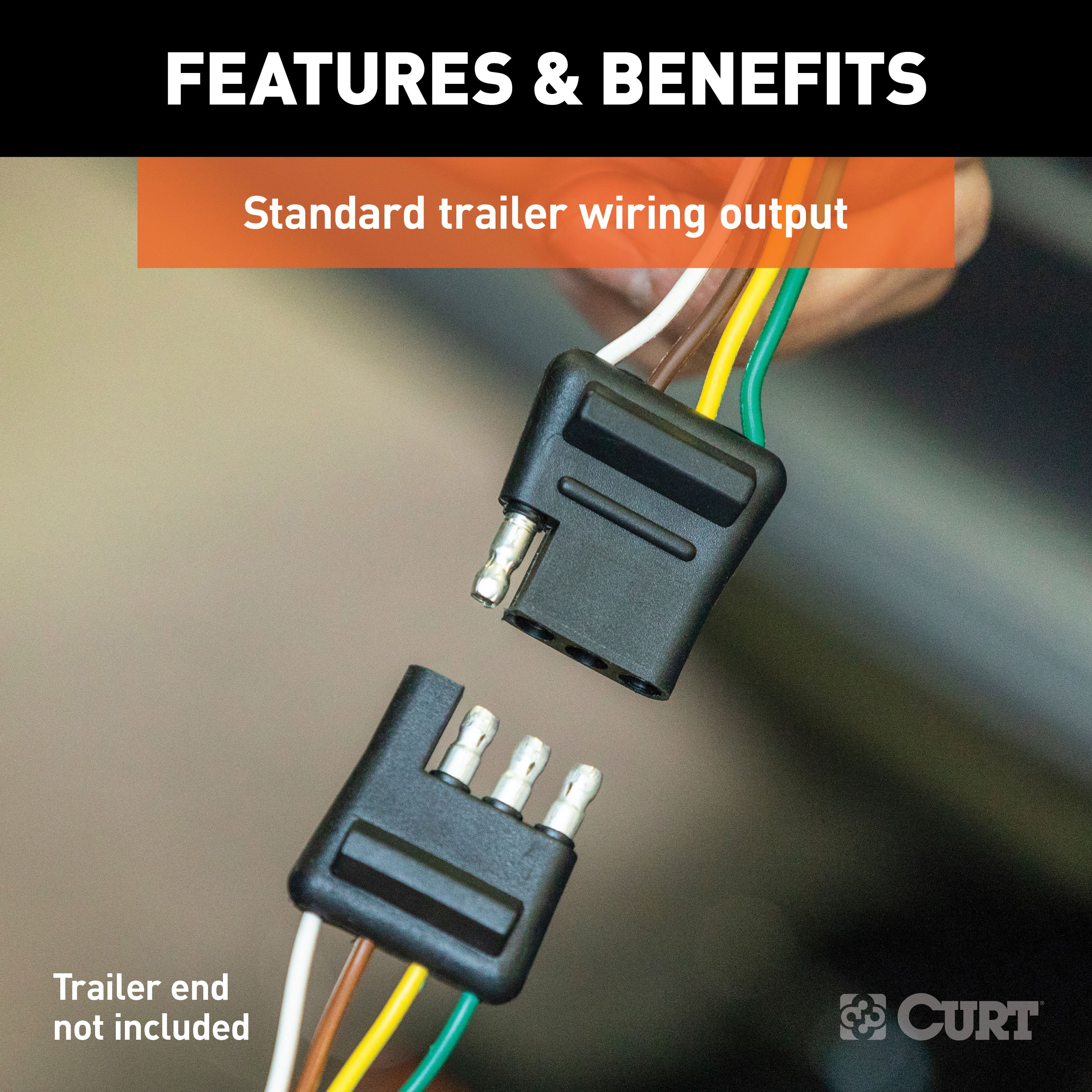
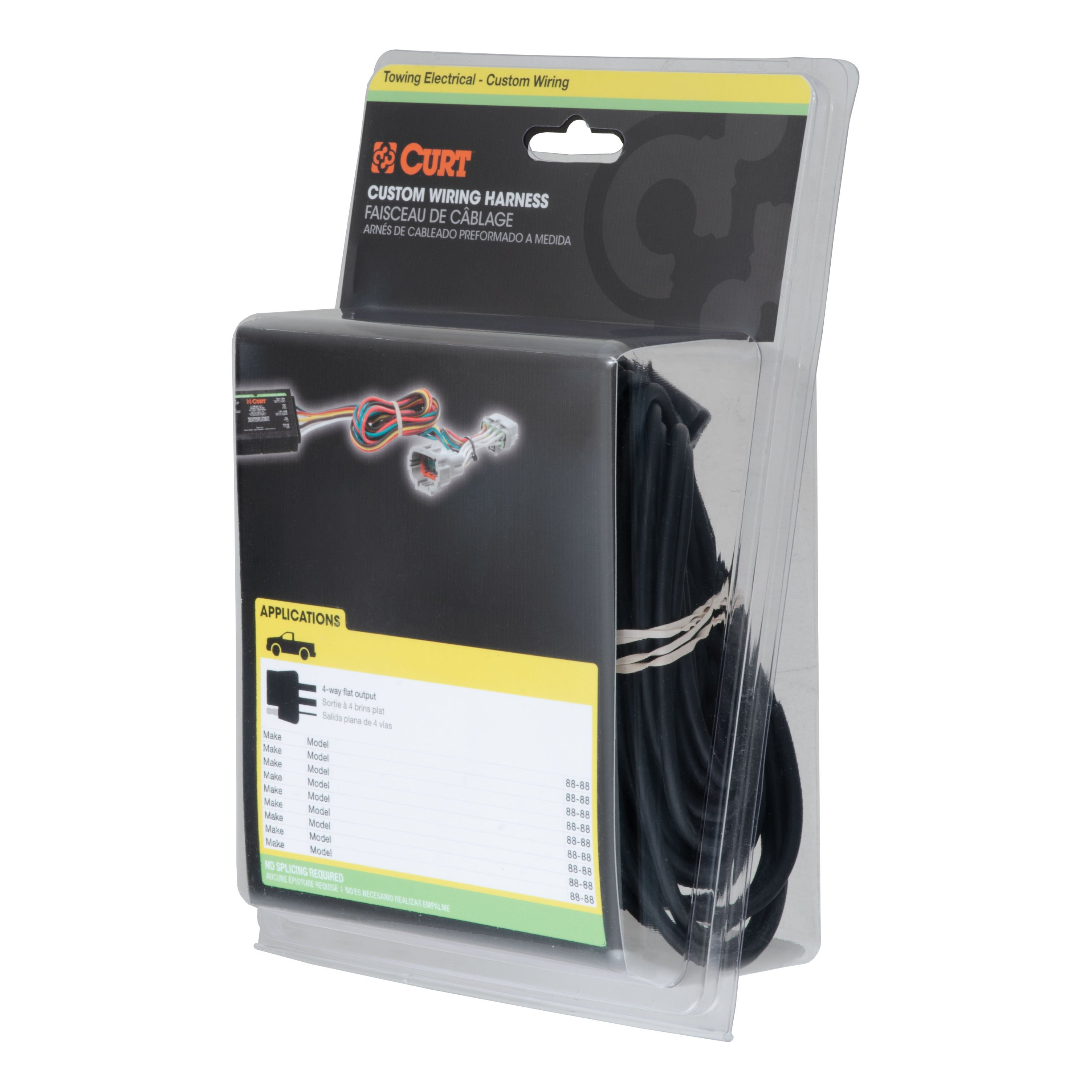
- Includes: Class 3 Trailer Tow Hitch, Custom Wiring Harness, 4-Way to 5-Way Flat Adapter for Boat Trailer Surge Brakes, Connector Mounting Bracket for 5-Way Flat
Compatibility Chart
Description
Get Expert Help
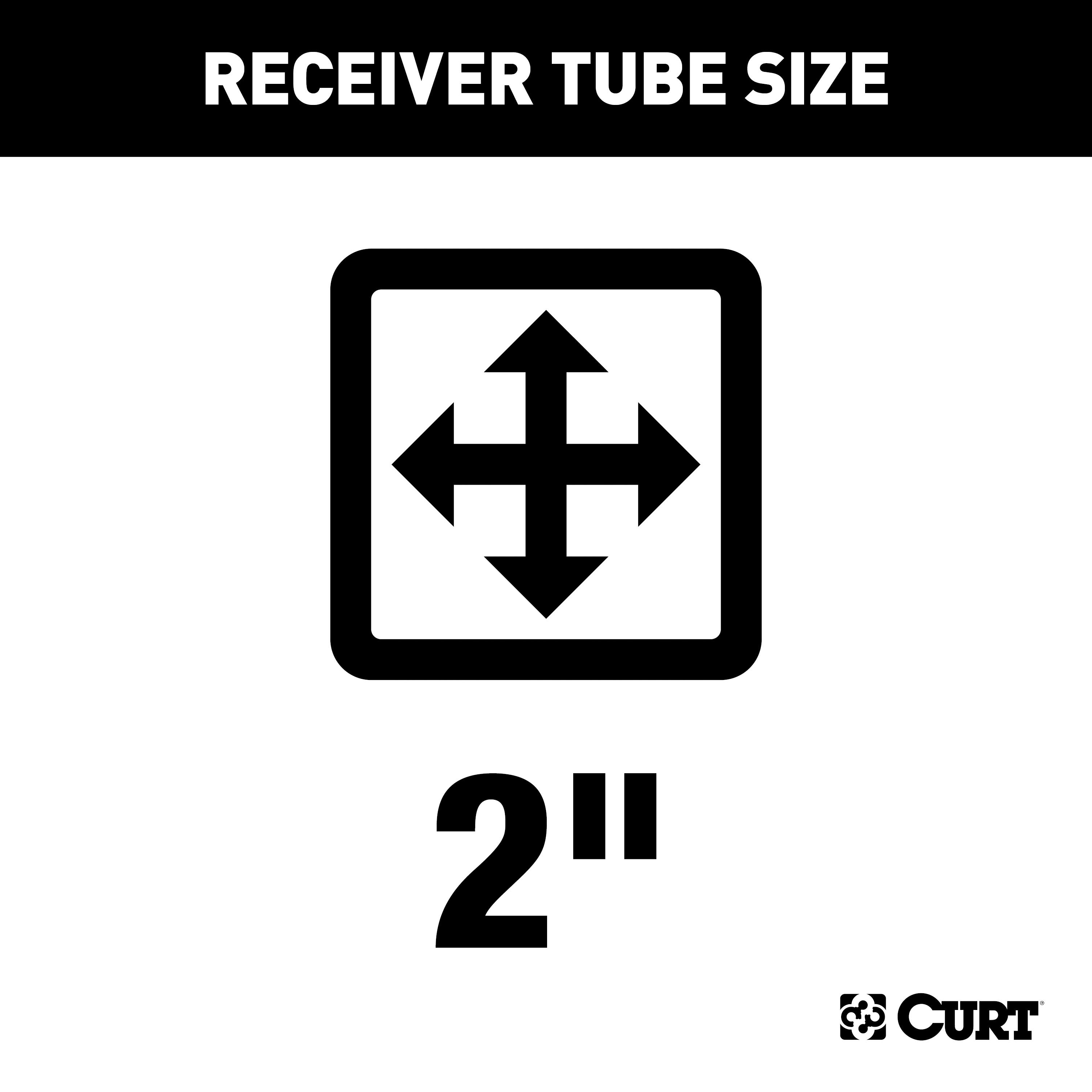
For 2015-2022 Ram ProMaster City Trailer Hitch + Wiring 5 Pin Fits All Models Curt 13215 2 inch Tow Receiver Install Notes
Installation Instructions for 2015-Present Ram ProMaster City Van
Part Number:
- 13215
Tools Required:
- Safety glasses
- Ratchet
- Torque wrench
- 15mm socket
- T27 Torx bit socket
- 12" socket extension
- Phillips screwdriver
Step-by-Step Instructions:
-
Remove Bottom Bumper Cover Fasteners:
- Using a T27 Torx bit socket, remove the three fasteners located at the bottom of the bumper cover.
-
Remove Wheel Well Fasteners:
- With a Phillips screwdriver, remove the ten fasteners located within the wheel wells.
-
Detach Top Bumper Cover Fasteners:
- Locate and remove the two fasteners at the top of the bumper cover, hidden behind the wheel well, using the T27 Torx bit socket.
-
Remove Additional Fasteners:
- Remove four top bumper cover fasteners and six taillight fasteners using the T27 Torx bit socket.
- Remove two final bumper cover fasteners located below the taillight assembly with the T27 Torx bit socket.
-
Detach Bumper Cover:
- Gently pull the sides of the bumper cover away from the vehicle until it detaches.
- Disconnect the harness at the bumper and set the bumper cover aside.
-
Remove Bumper:
- Using a 15mm socket, remove the six bolts securing the bumper.
- Set the bumper aside.
-
Install Hitch:
- Raise the hitch into position.
- Reinstall the bumper over the hitch, aligning all mounting points.
- Loosely install the factory bolts to hold the assembly in place.
-
Torque Fasteners:
- Torque all M10 fasteners to 45 ft-lbs to ensure secure attachment.
-
Reassemble Vehicle Components:
- Reinstall the bumper cover, reconnect the harness, and reattach the taillights by reversing the removal steps.
Safety Notes:
- Load Capacities:
- Weight Carrying: 3,500 lbs. trailer weight, 350 lbs. tongue weight.
- Warning: Never exceed your vehicle manufacturer's recommended towing capacity.
- Maintenance:
- Periodically check this receiver hitch to ensure all fasteners are tight and all structural components are sound.
- Warranty:
- CURT Manufacturing LLC. warrants this product to be free of defects in material and/or workmanship at the time of retail purchase by the original purchaser. Alteration, misuse, or improper installation voids the warranty. Liability is limited to repair or replacement of defective products and specifically excludes liability for incidental or consequential loss or damage.
For installation questions, contact Technical Support at 1-877-287-8634.
Installation Instructions for Ram ProMaster City
Part Numbers:
- 56270
Wiring Access Location:
- S3: Behind driver side rear access panel
- S4: Behind passenger side rear access panel
Tools Required:
- Panel trim removal tool
- Phillips screwdriver
- Wire stripper
- Crimping tool
- Side cutter
- Fish wire
- Right angle pick
Electrical Ratings:
- Signal Circuits: 7.5 amps per side
- Tail/Running Circuits: 7.5 amps total
Step-by-Step Instructions:
Step 1: Disconnect the Battery
- Locate the vehicle battery on the driver side under the hood.
- Disconnect the negative battery terminal to ensure safety during the installation.
Step 2: Prepare the Rear Cargo Doors
- Open the rear cargo doors.
- On the driver side, locate the yellow push latch and push it in to open the cargo door past 90°.
Step 3: Remove the Driver-Side Taillight
- Locate and remove the Phillips screws holding the driver-side taillight in place.
- Carefully pull the taillight outward to access the vehicle taillight wiring harness.
- Disconnect the connectors from the taillight housing, ensuring the locking tabs are not damaged.
Step 4: Install the Driver-Side Wiring Harness
- Insert the custom wiring harness end with the yellow wire into the top frame hole on the driver side.
- Use a fish wire to guide the wiring harness down the channel leading to the rear taillight connector.
- Route the yellow wire through the opening and connect it between the separated connectors on the taillight.
Step 5: Remove the Dome Light
- Inside the rear cargo area, remove the dome light above the cargo doors.
Step 6: Route the Passenger-Side Wiring Harness
- Run a fish wire into the top frame hole on the passenger side above the cargo door toward the center of the vehicle.
- Use the dome light hole to guide the fish wire to the driver side of the vehicle.
- Attach the custom wiring harness end with the green wire to the routed fish wire.
- Pull the green wire through to the passenger side and connect it as described in Step 4.
Step 7: Secure the Ground Wire
- Locate a suitable grounding point near the wiring connection, such as an existing screw with a nut in the vehicle frame.
- If no suitable point is available, drill a 3/32" pilot hole in a clean, rust-free, and paint-free area.
- Secure the white ground wire using the provided ring terminal and screw.
Safety Note: Always inspect for hidden components behind or under surfaces before drilling to avoid damage or injury.
Step 8: Mount the Converter Box
- Inside the cargo area, locate a flat spot on the upper corner inside the rear cargo door frame.
- Use the provided double-sided tape to adhere the black converter box securely to this location.
Step 9: Route and Connect the Power Wire
- Route the black power wire from the converter box to the vehicle battery.
- Refer to the provided CME-PCL-INS sheet for detailed guidance.
- Use cable ties to secure the wire along its route, avoiding pinch points, sharp edges, and hot or rotating components.
Step 10: Position the 4-Flat Connector
- Locate the 12V DC accessory port cover near the floor on the driver side and remove it.
- Route the 4-flat wire through the top frame hole where the converter is installed and out through the bottom of the 12V DC accessory hole.
- Reinstall the 12V DC accessory cover and coil the 4-flat wire for storage when not in use.
Step 11: Finalize Installation
- Reinstall all items removed during installation, including taillights, trim panels, and the dome light.
- Reconnect the negative battery terminal to restore the vehicle’s electrical system.
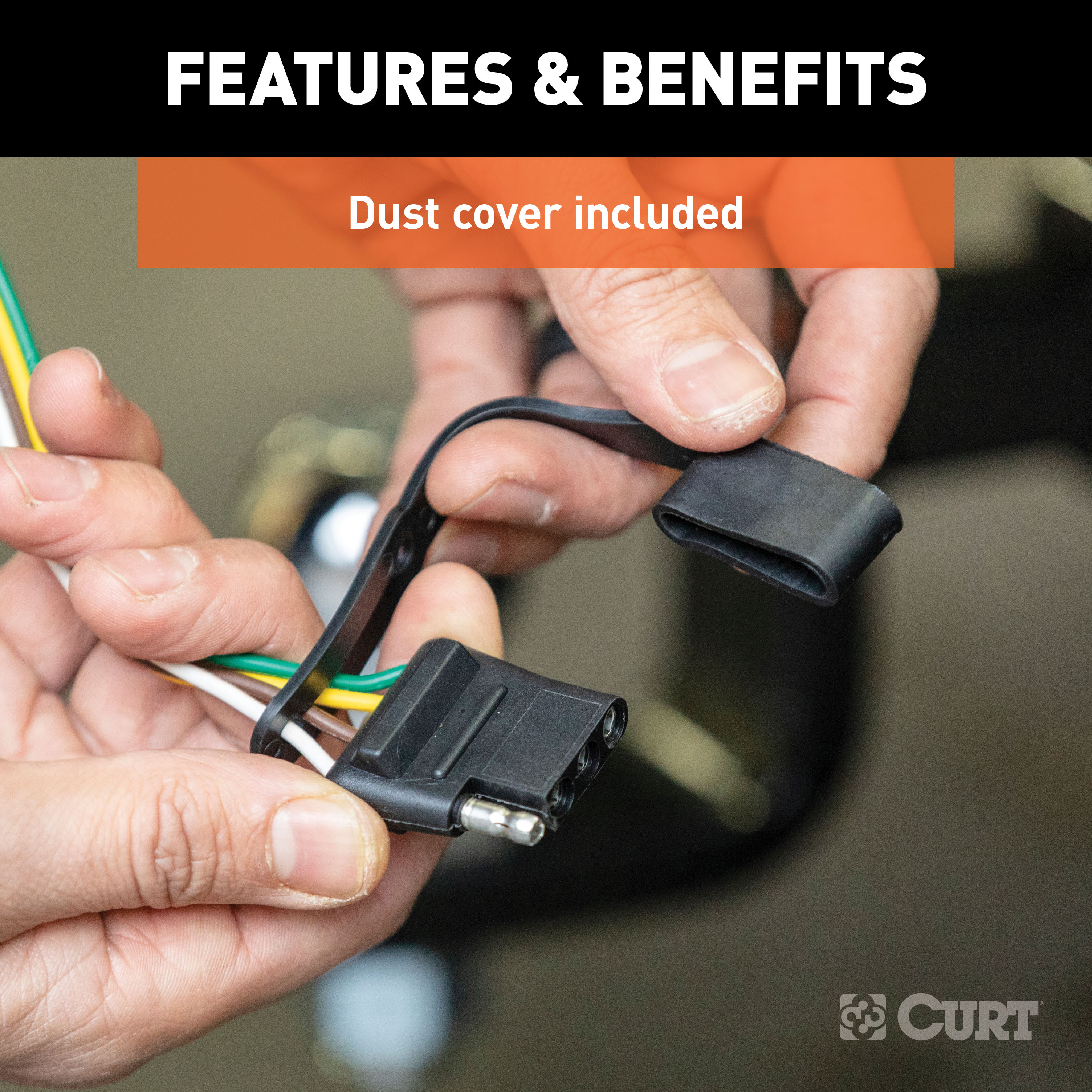
- Install the provided 4-flat dust cover to protect the connector from dirt and corrosion.
Hardware List:
- White ground wire with ring terminal
- Black converter box with double-sided tape
- 4-flat wiring harness
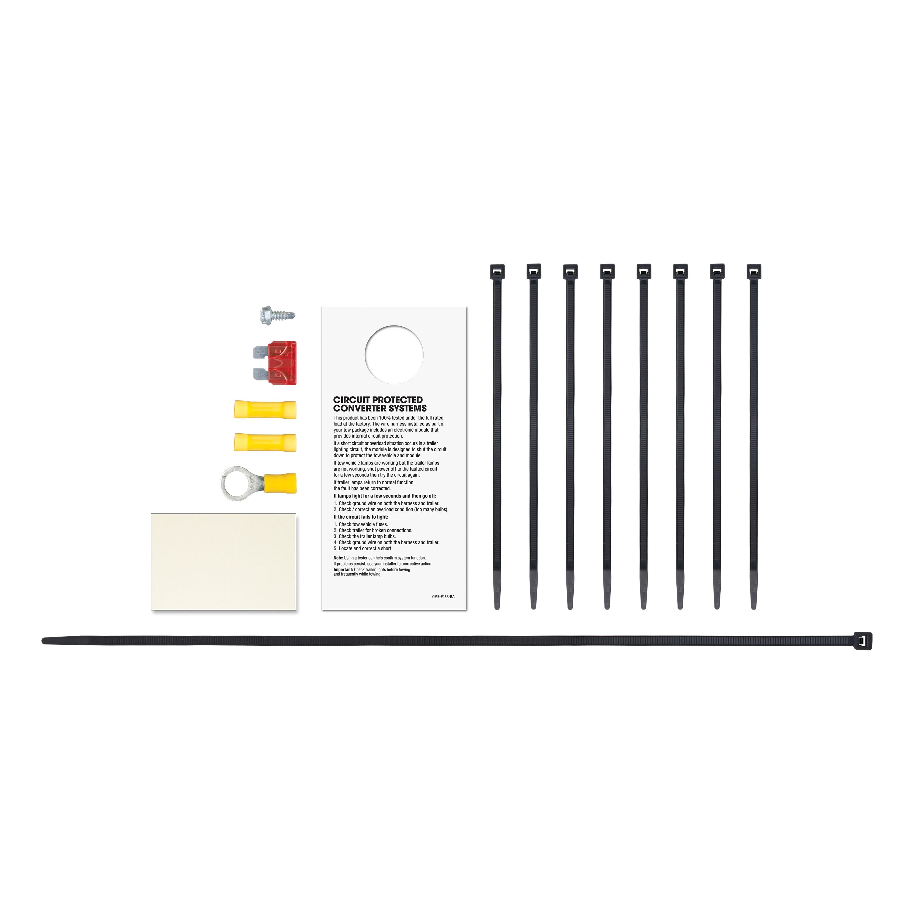
- Cable ties (provided)
Safety Notes:
- Ensure the battery connection is fuse-protected (maximum 10 amps). Exceeding this rating can lead to overheating, fire, or voided warranty.
- Inspect for hidden components before drilling to avoid damage or injury.
- Test for proper function by using a test light or connecting a properly wired trailer.
Specifications:
- System Compatibility: This converter system is to be used only on 12-volt negative ground systems.
Installation Instructions for 4-Way to 5-Way Adapter
Tools Required:
- Wire Crimpers
- Wire Cutters
- Test Light or Multimeter
- Quick Splice Connector (provided)
- Additional Wire (if needed for reverse light connection)
- Cable Ties (optional)
- Silicone Sealant (optional)
Overview:
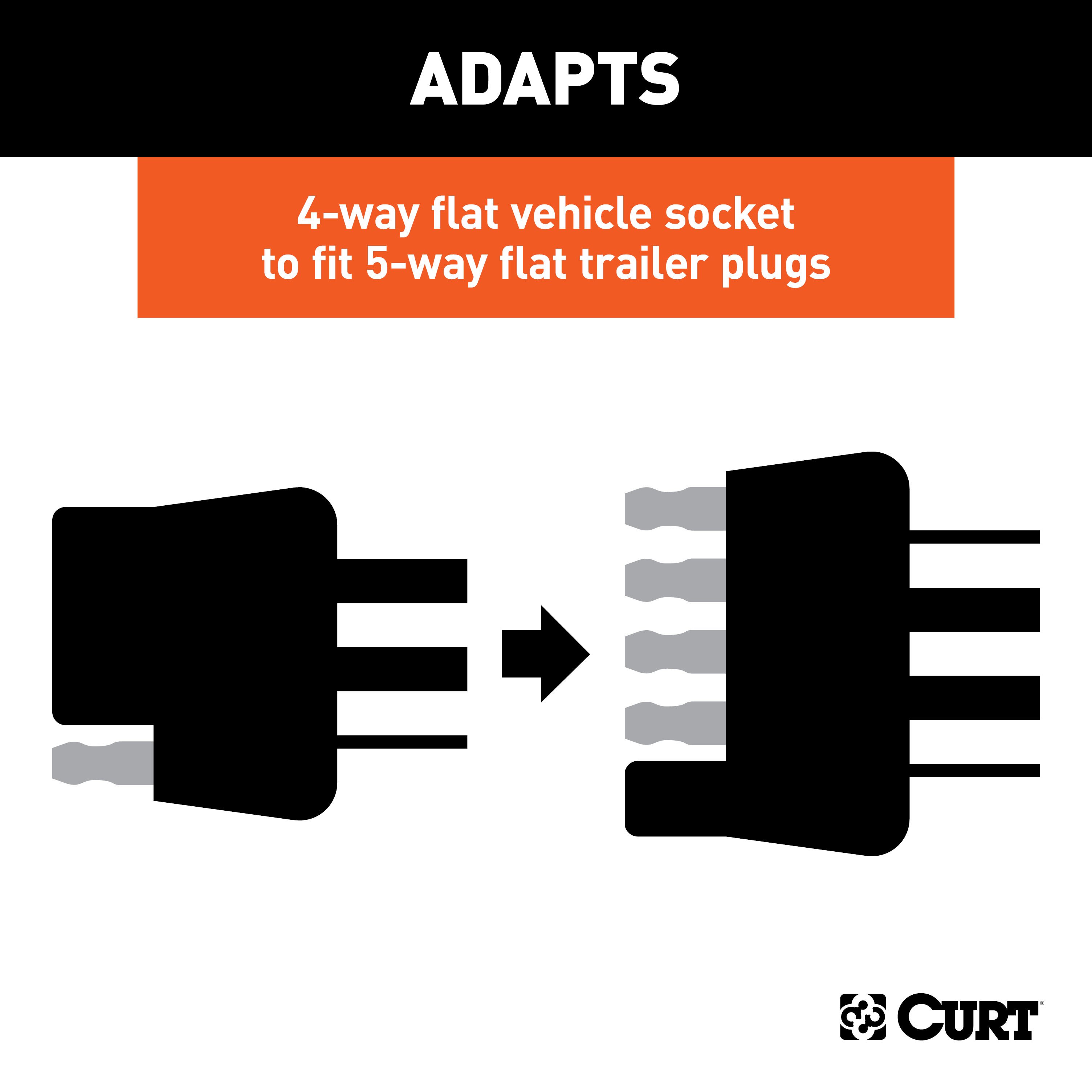
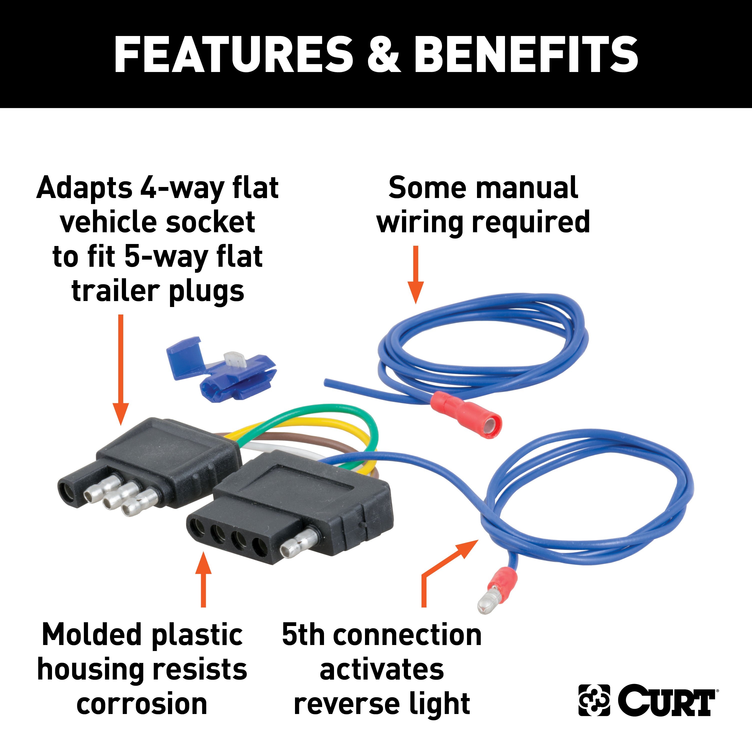
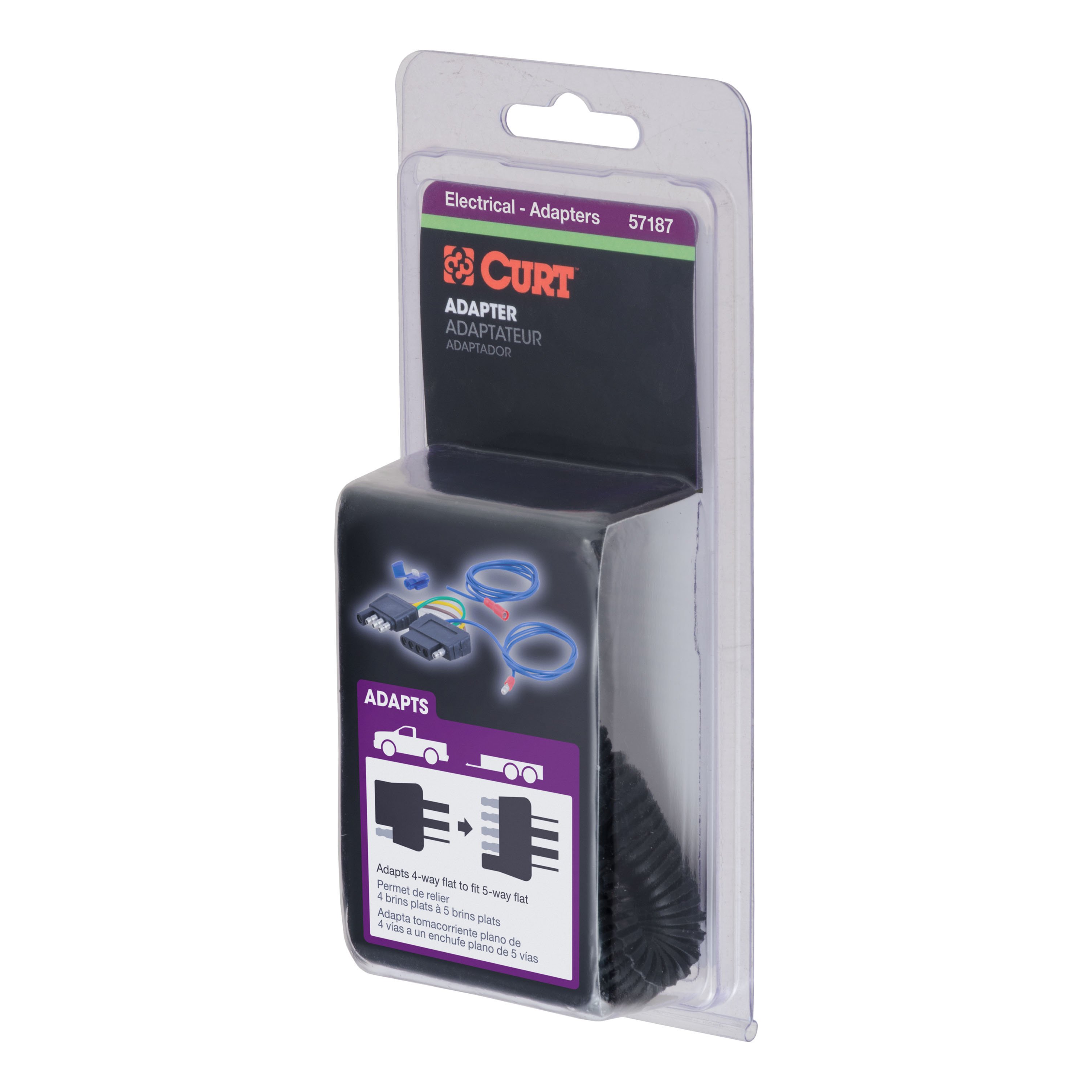
This adapter converts your 4-way flat trailer connector to a 5-way flat, adding reverse light functionality for trailers with reverse lights or surge brake lockout systems.
Step-by-Step Instructions:
1. Mount the Adapter:
- Select a suitable mounting location near the hitch and securely install the adapter.
2. Connect the 4-Way Plug:
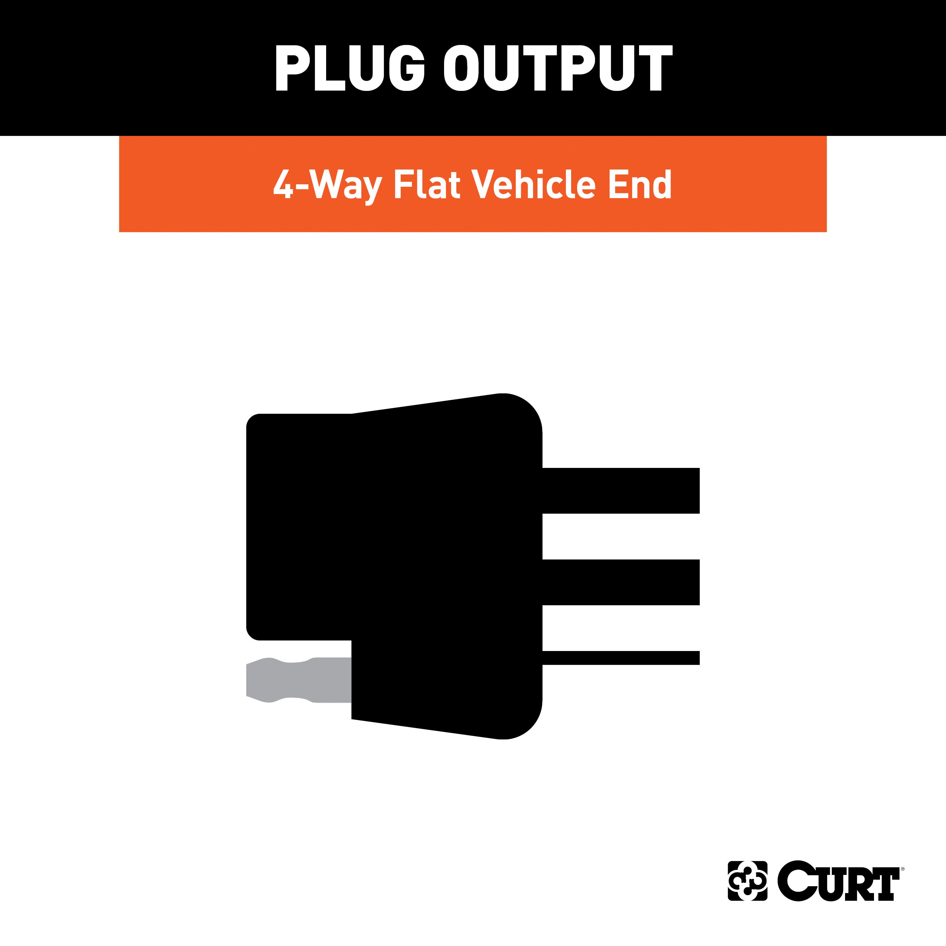
- Plug the 4-way flat connector from the adapter into the existing 4-way flat connector on your vehicle.
- This connection provides tail lights, left turn, right turn, and brake light functions.
3. Ground the Adapter:
- Locate a solid ground point near the adapter, such as the vehicle frame.
- Clean the surface to ensure proper contact.
- Secure the white ground wire from the adapter using the provided eyelet and a self-tapping screw.
4. Connect the Reverse Light Circuit:
-
Locate the Reverse Light Wire:
- Identify the reverse light circuit on your vehicle, typically found near the tail light assembly.
- Use the provided quick splice connector to attach the adapter's blue wire to the vehicle’s reverse light circuit.
-
Extend the Blue Wire (If Needed):
- If the adapter's blue wire is too short, splice in additional wire to reach the reverse light circuit.
- Route the wire safely, avoiding hot or moving parts, and secure it with cable ties.
-
Seal the Connection:
- If routing the wire through a grommet, seal any openings with silicone to prevent water ingress.
5. Secure the Wiring:
- Use cable ties to secure all wires and prevent them from hanging loosely or contacting sharp edges.
6. Test the Adapter:
- Plug the adapter into your trailer’s 5-way flat connector or use a test light to verify functionality:
- Brown Wire: Tail lights (solid when headlights are on).
- Yellow Wire: Left turn signal and brake light (flashes with turn signal).
- Green Wire: Right turn signal and brake light (flashes with turn signal).
- Blue Wire: Reverse light (active when the vehicle is in reverse).
- White Wire: Ground (continuity with the vehicle's ground).
Notes:
- This adapter is designed specifically for trailers requiring a reverse light or surge brake lockout circuit.
- Ensure all connections are secure to avoid intermittent functionality.
- Always follow safety guidelines during installation and verify all circuits before use.
Warning: Improper installation or overloaded circuits can result in damage or fire. Test all connections carefully.


